Introduction
After completing the Setup Wizard and defining your Geometry types, the cut parameters for each Metal sheet or Free teach node are configured on the Parameters tab. The Parameters tab is organised into three sections, in this order:
| Section | Purpose |
| Cut chart | Summary of the wizard selections and the detected hardware cartridge. |
| Optimization | Cut speed and AVC height-control settings. |
| Advanced | Touch sense, arc-on / arc-off macros, process settings, and corner blending. |
This guide documents each section in that order. Parameter ranges are listed; specific values come from the Hypertherm cut chart or from the wizard selection.
Cut chart
The Cut chart section shows a summary of the current wizard selections and the detected hardware cartridge.
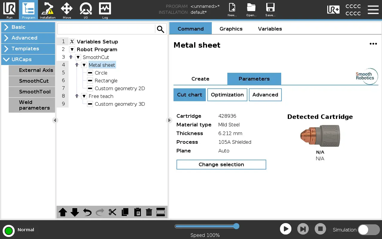
Selection summary
| Field | Description |
| Material | Material type selected in the wizard. |
| Thickness | Plate thickness selected in the wizard. Shows the effective thickness. |
| Bevel angle | Bevel angle configured in the wizard. |
| Cartridge ID | ID of the selected consumable cartridge. |
| Process name | Process associated with the cartridge. |
| Plane | Cutting plane (Auto or the named custom plane). |
| Detected cartridge | Cartridge ID reported by the Hypertherm hardware (SYNC only). |
Changing the selection
Press Change selection to re-open the wizard. The wizard opens on the Material type page with all previous selections pre-filled. Change any selection and complete the wizard again.
After completing the wizard, the Cut chart section updates to reflect the new selection.
Optimization
The Optimization section controls how fast the robot cuts and how it manages height control via AVC (arc voltage control).
Cut Type
| Mode | Description |
| Production | Uses preset speed values optimised for throughput. Speed fields are read-only. The values are based on the wizard selection and Hypertherm’s recommendations. |
| Quality | Uses preset speed values optimised for cut quality. Speed fields are read-only. The values are based on the wizard selection and Hypertherm’s recommendations. |
| Custom | All speed and reduction fields are editable. Custom values are remembered when switching between modes. |
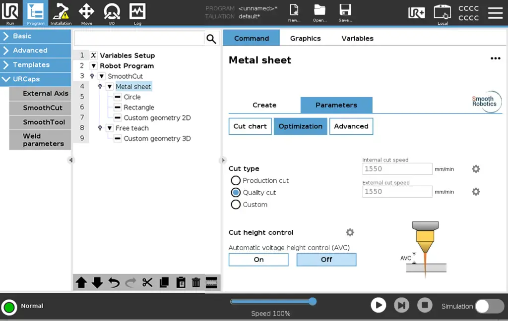
Internal and External Cut Speed
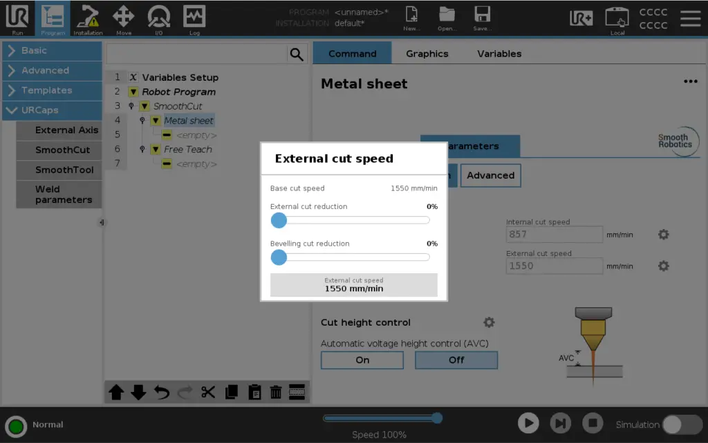
Internal and external cut speeds are set independently. On the Optimization section, open the Cut Speed Popup via the gear button next to each speed to set the value.
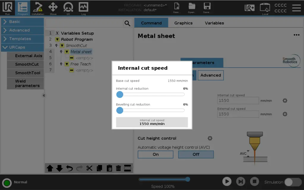
Cut Speed Reduction
Reduction percentages slow the robot down at corners and bevelled sections to improve cut quality.
| Parameter | Range | Default | Description |
|---|---|---|---|
| Internal cut reduction | 0 to 100 % | Based on percentage suggested by Hypertherm. | Speed reduction at internal corners. |
| External cut reduction | 0 to 100 % | Based on percentage suggested by Hypertherm. | Speed reduction at external corners. |
| Internal bevelling reduction | 0 to 100 % | Pre-set from the wizard bevel angle. | Reduction at bevelled internal corners. |
| External bevelling reduction | 0 to 100 % | Pre-set from the wizard bevel angle. | Reduction at bevelled external corners. |
ℹ️ Example: with an Internal cut speed of 400 mm/min and an Internal cut reduction of 50%, the robot slows to 200 mm/min at each internal corner.
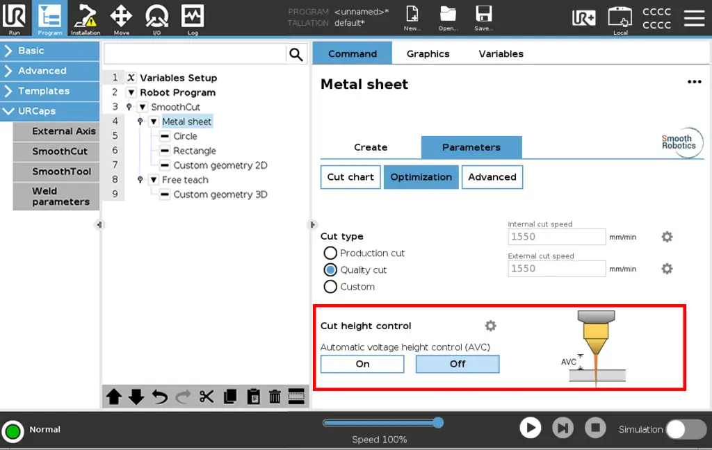
Cut Height Control – AVC
AVC (Automatic voltage height control) automatically adjusts the Z-axis distance from the plate during cutting based on arc voltage feedback. Without AVC, the robot holds a fixed Z-height throughout the cut.
| Parameter | Options |
| AVC (Automatic Voltage Height Control) | On / Off |
Off: the robot holds a fixed Z-height throughout the cut.
On: the Z-axis is continuously adjusted during cutting based on arc voltage feedback.
| ⚠️ IMPORTANT NOTE |
|---|
| Voltage divider ratio: For the best AVC results, set the voltage divider PCB on the Hypertherm unit to a 30:1 voltage ratio. This is the configuration SmoothCut is tested against, and it provides a cleaner voltage signal with less noise than the standard 50:1 ratio. For detailed instructions on how to change the voltage divider ratio on your machine, refer to the Powermax 65/85/105 SYNC™ Mechanized Cutting Guide, page 35. |
Cut height control parameters
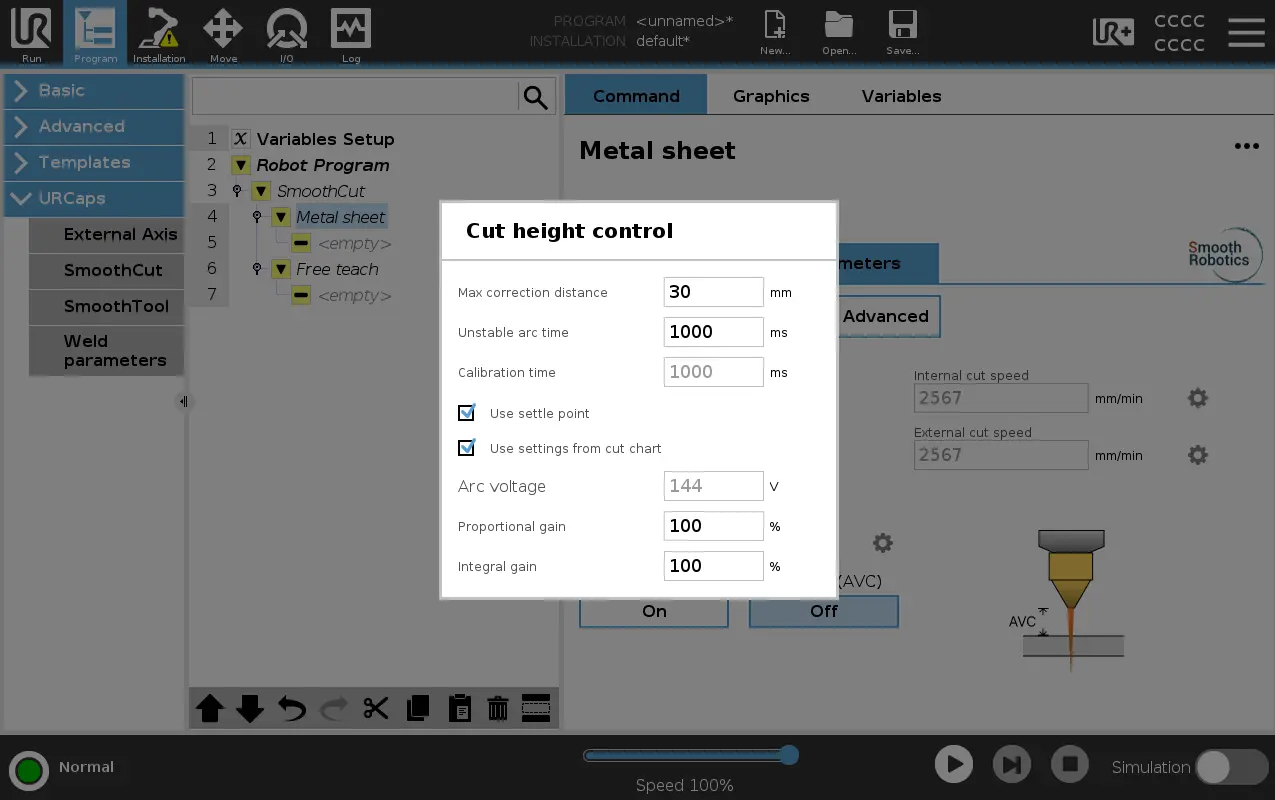
Open the Cut height control popup by pressing the gear button next to the title to configure the PI tuning, settle point, and target arc voltage.
| Parameter | Range | Description |
| Max correction distance | 0 to 50 mm | Maximum Z-axis correction AVC can apply. |
| Unstable arc time | 0 to 10000 ms | Wait time after arc-on before AVC correction begins. |
| Calibration time | 0 to 10000 ms | Duration of the baseline voltage calibration after the stability wait, used to derive the target settle point. Can be configured when Use settle point is not on. |
| Use settle point | On / Off | Use a fixed settle point instead of automatic calibration. With this enabled, Calibration time will be ignored. |
| Use settings from cut chart | On / Off | When on, Arc voltage is pre-set from the Hypertherm cut chart and cannot be edited. Turn off to enter a custom target arc voltage (v). |
| Arc voltage | Cut-chart value or custom (v) | The target arc voltage used when Use settle point is enabled. Read-only when Use settings from cut chart is on. |
| Proportional gain | 0 to 10000 % | Proportional gain of the PI controller. Pre-tuned by Smooth Robotics; advanced users can fine-tune. |
| Integral gain | 0 to 10000 % | Integral gain of the PI controller. Pre-tuned by Smooth Robotics. |
AVC Sequence
The AVC sequence on each cut follows this order:
Each cut runs the AVC sequence in this order:
- Arc fires.
- Wait Unstable arc time (arc stability wait).
- (Optional) Move to settle point if Use settle point is On.
- Calibrate for Calibration time (baseline voltage measured).
- PI correction active. Z-axis adjusts continuously to maintain the target arc voltage.
Tuning guidelines
| Symptom | Suggested adjustment |
| Z-axis oscillates or overshoots | Reduce Proportional gain. |
| Slow response to height changes | Increase Proportional gain or Integral gain. |
| Correction hits the limit too often | Increase Max correction distance. |
| Arc not stable before correction starts | Increase Unstable arc time. |
| Baseline measured before voltage settles | Increase Calibration time or enable Use settle point. |
Advanced
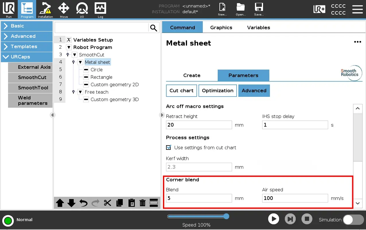
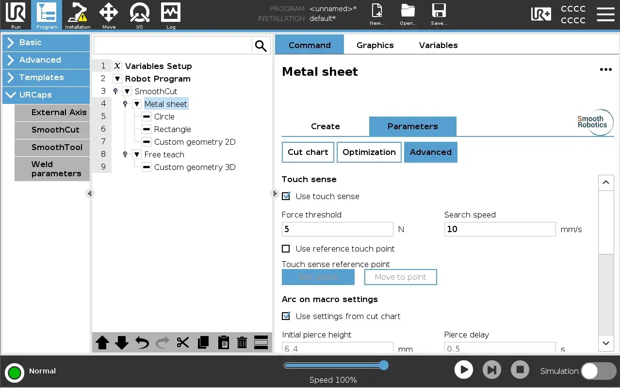
The Advanced section contains detailed parameters for touch sensing, arc-on and arc-off macros, process settings, and corner blending.
8.5 Touch Sense
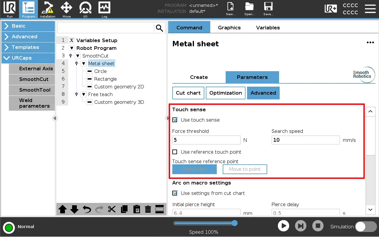
Touch sense probes the plate surface before each cut to find the actual material height, compensating for plate positioning variation.
| Parameter | Range | Default | Description |
|---|---|---|---|
| Use touch sense | On / Off | On | Enables surface probing before each cut. |
| Force threshold | 0 to 100 N | 5N | Contact force that stops the probing move. |
| Search speed | 0 to 50 mm/s | 10 mm/s | Speed of the probing approach move. |
| Use reference touch point | On / Off | Off | Use a reference point for height compensation across the plate. |
When Use reference touch point is enabled, teach a reference point on the plate surface using the Set point button. The Move to point button moves the robot to the taught reference point. The system measures the height at the reference point once per program run and compensates for plate tilt at each cut site.
⚠️ A validation error is shown if Use reference touch point is enabled but no reference point has been taught.
Arc on macro settings
These control what happens when the plasma arc is first established at the start of each cut.
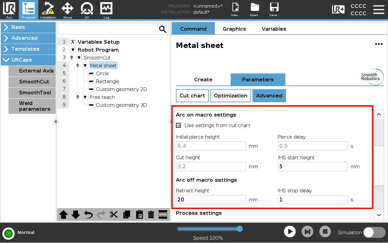
| Parameter | Range | Default | Description |
|---|---|---|---|
| Use settings from cut chart | On / Off | On | When on, all fields below are pre-set from the Hypertherm cut chart and cannot be edited. Turn off to enter custom values. |
| Initial pierce height | 0 to 50 mm | 3 mm | Torch height above material when the arc fires. |
| Pierce delay | 0 to 50 s | 1 s | Pause after arc-on before motion begins. |
| Cut height | 1 to 50 mm | 3 mm | Standoff distance from the material surface during cutting. |
| IHS start height | 1 to 50 mm | 3 mm | Height above the surface where IHS probing begins. |
Arc off macro settings
| Parameter | Range | Default | Description |
|---|---|---|---|
| Retract height | 1 to 50 mm | 3 mm | Height the torch lifts to after each cut. |
| IHS stop delay | 0 to 10 s | 1 s | Pause at the end of a cut before arc-off. |
Process settings
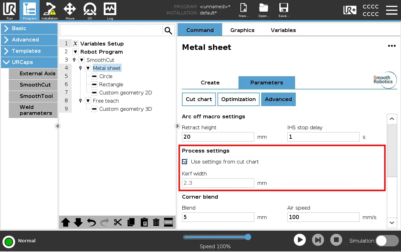
| Parameter | Range | Default | Description |
|---|---|---|---|
| Use settings from cut chart | On / Off | On | When on, Kerf width is pre-set from the cut chart and cannot be edited. Turn off to enter a custom value. |
| Kerf width | 0 to 50 mm | 0 mm | Total kerf width. The path is offset by half this value. |
Kerf compensation offsets the tool centre path to account for material removed by the plasma jet. Kerf compensation behaviour:
- External cuts: the path offsets outward by the kerf width.
- Internal cuts: the path offsets inward by the kerf width.
- Set Kerf width to 0 for no compensation.
Customization of Kerf width is only possible when ‘Use settings from cut chart’ is not checked.
Corner blend
| Parameter | Range | Description |
| Blend | 0 to 500 mm | Blend radius applied at path corners. |
| Air speed | 1 to 250 mm/s | Robot travel speed during non-cutting moves. |